Saturday, 23 June 2012

3D Printed Wheels. A First Attempt

Hello.

Today has been an interesting one. After a 'pep talk' from a fellow member of the 2mmSA Oxford Group with regards to my 3D printed wheel centers I then realised that I had enough bits to make a set of replacement wheels for a Graham Farish Pannier Tank. Below is what I managed to achieve in about 5 hours today...

Here are the ingredients for the conversion.
  1. A Graham Farish Pannier Tank Engine
  2. Some 1.5mm steel rod
  3. A couple of etched coupling rods from the 2mmSA (3-205)
  4. 6 x 3D printed spoked wheel centers.
  5. 6 x 9mm Steel wheel rims (courtesy of the 2mmSA)
  6. 6 x 2mmSA Crankpins (I used 3-106 but 3-107 would be better (I didnt have any!))
Step 1 was to press the wheel centers onto the rims. This was done simply by using (a very rusty!) machine vice and the centers were pressed into the rims until the back of the wheel was flush.

Step 2 was to cut 3 lengths of the steel rod for the wheel axles. I cut them with at least 10mm extra than I needed (for holding). I then used my rotary tool to clean up the ends and add a small chamfer to ease pressing on the wheels.

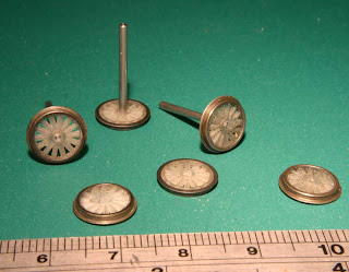
Step 3 was to press the axle onto the wheel. I used my drill press to make sure everything stayed square. I pushed the axle about 5mm through the wheel. I ended up with this...

Step 4 was to press the second wheels onto the axle. I did this by first holding the 5mm length of axle in the check and then pressing the second wheel on until it was on the axle. I then used a small length of tube which was a sliding fit over the axle and using a back-to-back gauge, pressed the wheels together until the gauge was a good fit between the wheels.

Im going to mention the gear now too. I 'salvaged' it from the original wheels as I didnt have an alternative but then found out that it had a bore of 1.6mm! Im not going into too much detail about how I got it to fit the axle (it was a bit of a cobble!) but it was pressed onto the axle of one wheelset before the second wheel was fitted in much the same way.

I then ended up with wheels like in the photo above. The pair nearest the ruler shows the next steps 5 where I cut the axle flush with the wheel (well cut it not quite flush then filed it down), then step 6 where I fitted the crankpins but pushing them through from the back with a bit of superglue to hold them in place.

Step 7 was them to paint them buy first giving the wheels a good clean in some IPA and then once dried I painted them with some Humbrol matt black.

Fitted into the chassis they look like this...

And below is how far I have got today. I still have a bit of work to do soldering the coupling rods in place but you get a good idea of the finished thing...


Julia :)


Monday, 18 June 2012

The Point Rodding Saga Continues...

Hello.

One of the 'smart' ideas I had for Highclere was to add point rodding to the layout. Its something that you dont see that often on layouts, especially in 2mm Scale. Little did I know how much of a pain it would turn out to be!

Now for a little background info for those who dont know what I am on about...

The point rodding for the layout is based around two parts. The first is some 0.4mm square Nickel-Silver wire which I buy from Model Signal Engineering, it comes in a pack of 10 x 12" lengths. The second part are the 'stools' which I persuaded Ivan from Southwark Bridge Models to etch, reduced from his 4mm scale range. Trust me, it took some persuading as they are VERY small! Below is a picture on how they come.


Using a collection of jigs I then solder the stools at 12mm intervals along the length of the square wire. For each point I have used 2 lengths of wire, one for switching the point and the second for locking it in place. This is the time consuming bit as each stool is individually soldered in place, for each 12" length of 2 point rods there are roughly 75 point rodding stools. The stools are then soldered onto a small section of PCB and then glued to a similar section of plastic to represent the concrete plinths they are mounted on in real life. The picture below shows you roughly what I mean.


To me though, its worth the effort. Once its painted and on the layout it adds another little bit of detail that helps it come to life.

The thing is though I have been working on this now for what seems an eternity! I am now concentrating on the area of the layout where the majority of points are so there is quite a bit of rodding to do. Considering that currently its taking around 3-4 hours to complete a 12" length of rodding its keeping me busy!

I have tried about 5 different jigs now to assemble the rodding, the jig below I made out of cardboard which I made because as the point rodding gets closer to the signal box on the layout it gains more rodding as its passed more points.


At the moment Im working on 4 rods in parallel as the picture below shows.


The saying "practice makes perfect" is so true! I havent given up yet....

Julia :)

Saturday, 16 June 2012

Hello and Welcome...

Hello.

For a while now I have wanted a home where I can post my modelling stuff. Why it has happened now I havent a clue but I am happy I have finally done it. Fingers crossed this will becomme the place where I post bits and pieces on my modelling which, right now is pretty much exclusively to 2mm:1foot. Right now things are fucused around my 2mm Finescale layout 'Highclere' based on the station just south of Newbury on the Didcot, Newbury, and Southampton Railway...


Thats just a random selection of photos, one thing Highclere is, is well documented! I am sure that these photos are not unfamiliar to many but in time, once things have settled down a little, there will be new and exciting things appearing here...

Julia :)